
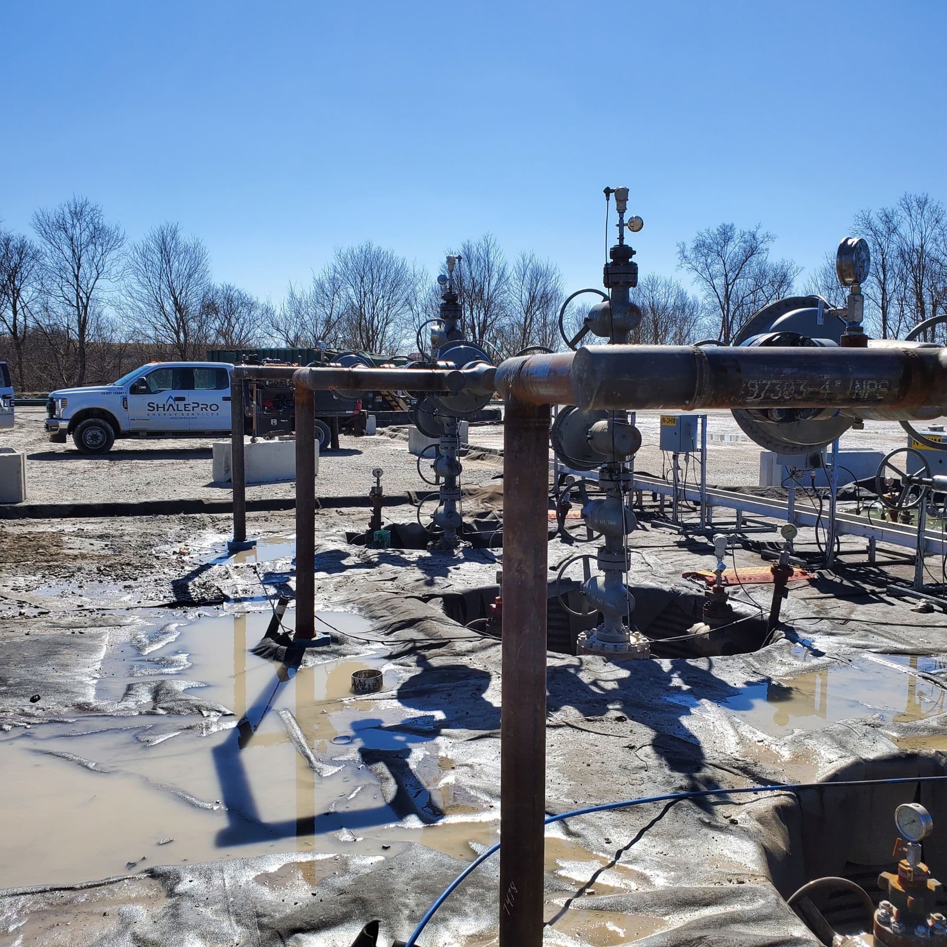
Yes, helical pile foundations reduce vibration reaching discharge piping at compressor exits. They transfer cyclic compressor loads deep into stable soil or bedrock and decouple the equipment base from adjacent pipe supports, interrupting the vibration path before it fatigues welds and flanges. That is the short version. The field reality has more moving parts.
Compressor discharge piping is where vibration failures cluster. Reciprocating and screw units pump cyclic energy into everything they touch, and the piping right off the exit takes the worst of it. Most operators reach for pipe supports, dampeners, or a layout redesign first. Those help. But the foundation under the machine is part of the same transmission path, and it usually gets ignored.
This guide covers how vibration travels from the compressor to the weld, how helical piles interrupt that path, what a retrofit looks like at a live station, how Appalachian Basin soils shape pile design, and how the foundation ties into the pipe stress model. ShalePro performs mechanical construction, compressor operations, and helical pile installation in-house, which gives crews field-level visibility into vibration failures at discharge points.
Do helical piles reduce pipe vibration at compressor exits?
Helical piles reduce pipe vibration at compressor exits by carrying equipment loads past compressible surface soils into stable strata and by separating the equipment base from the supports that hold the discharge piping. That two-part effect attacks the problem at the source rather than only downstream.
Think of the foundation as one link in a chain that runs from the compressor crankshaft to the nearest pipe weld. Pipe-side fixes like clamps, dampeners, and rerouting shorten or stiffen the downstream links. A helical foundation works on the upstream link, the base the machine sits on.
These approaches complement each other. A helical system does not replace good pipe support design, and good pipe support design does not fix a foundation that amplifies movement. Operators who treat vibration as a whole-path problem get better results than those who chase one symptom at a time.
How does compressor vibration reach discharge piping?
Compressor vibration reaches discharge piping through a physical path: cyclic forces move from the machine through its mounting bolts into the foundation, then into the soil and any structure sharing that mass, and finally into pipe supports anchored to the same ground.
Reciprocating units are the worst offenders because each stroke generates unbalanced forces and gas pulsation. Vibrations of compressor station piping are a documented reliability problem, driven by both mechanical shaking and pressure pulsation in the gas stream (OSTI journal record). Screw compressor outlets show similar pulsation-driven piping vibration that has to be analyzed and controlled (ResearchGate study).
The transmission path from equipment to weld
The path starts at the mounting bolts and runs into whatever the machine bears on, a concrete pad, a pile cap, or a grade beam. That foundation transmits energy into the surrounding soil and into any structure resting on the same mass.
Discharge piping frequently anchors to supports that bear on that same foundation or the adjacent grade. When that happens, the pipe is mechanically coupled to the machine, and equipment vibration flows straight into pipe stress.
Where fatigue shows up first
Fatigue shows up first at the stiff, stress-concentrating points near the compressor: welds, flanges, small-bore instrument connections, and threaded fittings. Root-cause work on compressor piping failures repeatedly traces cracks back to vibration-induced fatigue at these locations (Wood knowledge center).
ShalePro operates hundreds of compressors and performs maintenance across the basin, so crews see these fatigue failures firsthand. Small-bore connections are notorious. A half-inch drain or gauge line can crack through in months when the run behind it is shaking.
How do helical piles work as vibration isolation?
Helical piles work as vibration isolation by creating a discrete, deep load path that bypasses the loose surface soils that amplify movement and by allowing the equipment base to be structurally separated from the pipe supports.
Deep load transfer past compressible soil
Helical piles carry equipment loads through helical bearing plates into stable soil or bedrock, past the loose or compressible layers near the surface. Those surface layers are exactly where vibration gets amplified and where a shallow pad can rock or settle unevenly.
The pile shaft and plates form a load path with a different stiffness than a monolithic concrete block. That change in stiffness helps dissipate some vibration energy rather than transmitting it wholesale. A smaller footprint and discrete load points also shrink the soil zone through which vibration propagates to neighboring structures.
Decoupling the pipe supports from the equipment base
Pile caps can be designed with isolation materials or deliberate structural breaks that separate the compressor base from adjacent pipe supports. Rather than pouring one slab that everything shares, the design can put the machine on its own pile group and the pipe supports on another.
Break the shared mass, and you break the shortest path vibration takes from the machine to the pipe weld.
This is where the answer to the common search question, what are helical piles used for, meets vibration engineering. The same deep load transfer that stabilizes a foundation on weak soil also lets engineers isolate one load path from another.
Can helical piles be installed at an operating compressor station?
Yes, helical piles can be installed at an operating compressor station, often without shutting the unit down. They install with hydraulic torque equipment and need no concrete curing time, so foundation elements can carry load almost immediately after installation.
Speed and minimal excavation
Compared with drilled piers or driven piles, helical installation involves minimal excavation and no wet concrete. That reduces site disturbance, cuts the volume of spoils to manage, and often lightens the permitting burden. For a live station, less digging near active piping and electrical runs is a direct safety benefit.
Here is a typical phased retrofit sequence:
- Survey the site, locate buried utilities and piping, and lay out new pile positions clear of live lines.
- Advance helical piles with a torque motor while monitoring torque against design capacity.
- Set pile caps and any isolation details for the new supports.
- Load test and confirm torque correlation before transferring any load.
- Transfer equipment or pipe support load to the new foundation, then commission and monitor vibration.
Phased work around live piping
Work proceeds in phases so the compressor keeps running while new supports and caps go in. Crews position torque equipment to clear active piping and electrical systems, and load testing plus torque correlation confirm capacity before any equipment or pipe load transfers.
ShalePro offers 24/7 emergency response with crews positioned across the Appalachian Basin and performs helical pile installation and mechanical construction in-house, so one team coordinates the full retrofit scope. Work around live compressors still runs on a thorough Job Safety Analysis and daily tailgate meetings, consistent with OSHA oil and gas extraction expectations and PHMSA pipeline safety rules.
How do Appalachian Basin soils affect pile design?
Appalachian Basin soils affect pile design by dictating helical plate size, spacing, and embedment depth, because subsurface conditions swing from stiff clay to weathered shale to shallow bedrock, sometimes across a single pad.
From stiff clay to shallow bedrock
Basin soils commonly range from stiff clay to weathered shale, and bedrock can sit close to the surface. Helical plate diameter and spacing adapt to the bearing capacity and torque resistance the crew actually encounters during installation, not just the number on a boring log.
When a pile hits bedrock refusal, the design may switch to a smaller diameter shaft that can penetrate further or adjust pile spacing to spread the load. Frost depth and groundwater conditions drive embedment depth and bracket design, since a pile that heaves with frost or corrodes at the waterline does not stay stable.
Torque monitoring and refusal
Torque monitoring during installation is the field verification method. Installation torque correlates to pile capacity, so crews watch the torque reading and check it against design loads as each pile advances.
| Factor | Field condition | Design response |
|---|---|---|
| Bearing soil | Stiff clay to weathered shale | Standard helical plate sizing, torque-verified |
| Bedrock depth | Shallow or refusal | Smaller shaft, adjusted spacing |
| Frost line | Seasonal freeze zone | Deeper embedment below frost |
| Groundwater | High or fluctuating table | Corrosion allowance, bracket detailing |
ShalePro operates across Pennsylvania, West Virginia, Virginia, and Tennessee, so local crews know basin subsurface conditions and what the torque motor is likely to hit. Foundation practice for helical systems is documented by the Deep Foundations Institute.
Integrating foundation, pipe stress, and long-term performance
Foundation and pipe stress must be designed as one system, because helical pile stiffness and support locations directly change the loads and stresses the discharge piping sees over its life.
Feeding pile stiffness into the stress model
The pipe stress engineer has to account for foundation stiffness and support positions in the model. Helical pile capacity and deflection feed the support design, and the results feed back into whether the piping meets ASME B31 process piping stress limits.
Differential settlement between piles on the same pipe run can introduce new stresses. Connection integrity and alignment matter over time, not only on day one.
Performance under cyclic loading
Helical piles hold up under cyclic loading when they are properly sized and installed to target torque. But they are not maintenance-free. Periodic inspection checks bolts, cap cracking, and settlement, and vibration monitoring before and after a retrofit confirms the system is still doing its job.
Some sites still need isolation pads or spring mounts working with the helical foundation. Both OEM vibration limits and pipe code stress limits apply, and the design has to satisfy both.
Single-source delivery from foundation to tie-in
Splitting foundation and mechanical scopes across separate contractors adds coordination risk right at the interface where vibration failures start. A contractor who installs helical piles and fabricates pipe in-house can design the foundation-to-pipe interface as one system.
ShalePro Energy Services is an energy and industrial services company serving the Appalachian Basin from Houston, Pennsylvania, specializing in mechanical construction, pipe fabrication, helical pile installation, and operations and maintenance. Its mechanical technicians and project managers coordinate foundation work with fabrication at the West Alexander shop and stress calculations, then provide long-term operations and maintenance across hundreds of compressors as one accountable team from site prep through maintenance.
For related reading, see helical pile installation services, compressor station operations and maintenance, pipe fabrication capabilities, and pipe support design for vibration control.
Frequently Asked Questions
How do helical piles compare to concrete pads for compressor foundations?
Monolithic concrete pads are simple but transmit vibration directly into pipe supports and are hard to retrofit. Helical piles carry load to deep stable strata, install without curing time, and can be decoupled from adjacent structures. That makes them better suited to vibration-sensitive retrofit work at operating compressor stations.
What are helical piles used for besides vibration control?
Helical piles support compressor and equipment foundations, pipe racks, tanks, buildings, and structures on weak or variable soils. Field crews use them wherever fast, deep, low-disturbance load transfer is needed. That includes retrofits at operating oil and gas sites where excavation and concrete curing time are not practical.
Do helical piles require maintenance after installation?
Yes. Long-term performance depends on maintaining pile-to-cap and cap-to-equipment connections and avoiding differential settlement. Periodic inspection checks for loose bolts, cap cracking, and settlement signs. Vibration monitoring before and after the retrofit confirms the system is still performing to the design intent under cyclic compressor loading.
How is helical pile capacity verified during installation?
Installers monitor torque as the pile advances, since installation torque correlates to bearing capacity. That reading is checked against design loads throughout driving. Load testing confirms performance before any equipment or pipe weight transfers to the new foundation elements, so capacity is proven, not assumed.
Can vibration mitigation reduce leak and safety risk near compressors?
Yes. Vibration-driven weld cracking and flange leaks are real fire and release hazards near compressors. A stable, decoupled foundation lowers that risk. Work around live compressors still demands a thorough Job Safety Analysis and daily tailgate meetings to control the site-specific hazards that come with any live retrofit.
The bottom line
Compressor discharge piping fails at welds and small-bore connections because vibration travels through the foundation as much as through the pipe. Helical piles interrupt that path at the equipment base, carry load past unstable surface soils, and let engineers decouple the machine from the pipe supports. Paired with sound pipe stress design, they cut fatigue risk and the leak hazards that come with it.
Getting the foundation-to-pipe interface right takes one team that owns both scopes. Talk to ShalePro about helical pile installation and compressor vibration mitigation at contact ShalePro Energy Services.
Sources
Vibrations of compressor station piping (OSTI)
Vibration Issues Affecting Gas Compressor Facilities (Wood)
Vibration analysis and control of a screw compressor outlet piping system (ResearchGate)